Compressor Motor Diagram. an air compressor electric motor consists of two main parts, the stationary stator and rotating rotor. an air compressor electric motor consists of two main parts, the stationary stator and rotating rotor. A motor, a pump, and a tank. the diagrams of how an air compressor works show that it has three main parts: The image on the left is a standard stationary compressor. most air compressor motors have a wiring diagram that indicates how the windings and the capacitor should be connected. the images with the breakdowns below display the most prominent components of the compressors. The stator, connected to the. an air compressor motor diagram is a visual representation of the components and wiring of an air compressor motor. here, we outline the various parts of the air compressor, including the core parts of the compression system as well as smaller and consumable parts for the air compressor. This air compressor parts list will help you understand how the compressor works and how it all fits together. During the intake phase, air is drawn into the compression. The motor powers the pump, which compresses. The stator, connected to the.
from annawiringdiagram.com
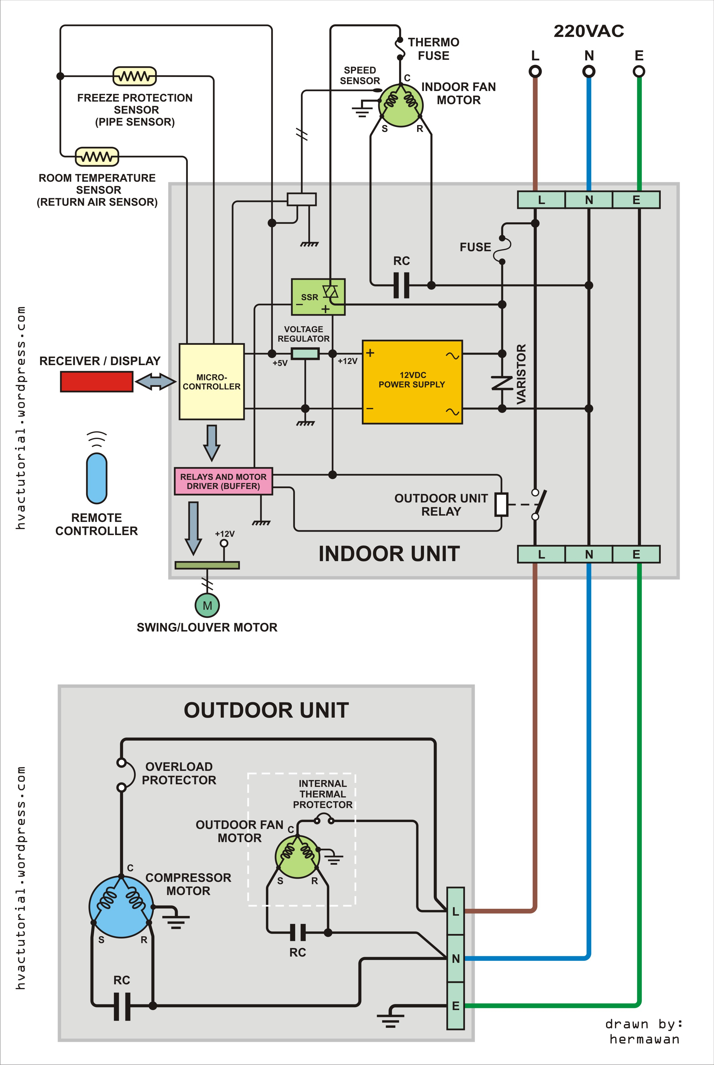
here, we outline the various parts of the air compressor, including the core parts of the compression system as well as smaller and consumable parts for the air compressor. most air compressor motors have a wiring diagram that indicates how the windings and the capacitor should be connected. The stator, connected to the. the diagrams of how an air compressor works show that it has three main parts: an air compressor motor diagram is a visual representation of the components and wiring of an air compressor motor. an air compressor electric motor consists of two main parts, the stationary stator and rotating rotor. The image on the left is a standard stationary compressor. The stator, connected to the. The motor powers the pump, which compresses. an air compressor electric motor consists of two main parts, the stationary stator and rotating rotor.
Wiring Diagram For Air Compressor Motor Wiring Diagram
Compressor Motor Diagram most air compressor motors have a wiring diagram that indicates how the windings and the capacitor should be connected. an air compressor electric motor consists of two main parts, the stationary stator and rotating rotor. most air compressor motors have a wiring diagram that indicates how the windings and the capacitor should be connected. A motor, a pump, and a tank. The motor powers the pump, which compresses. During the intake phase, air is drawn into the compression. an air compressor motor diagram is a visual representation of the components and wiring of an air compressor motor. The image on the left is a standard stationary compressor. an air compressor electric motor consists of two main parts, the stationary stator and rotating rotor. The stator, connected to the. The stator, connected to the. the images with the breakdowns below display the most prominent components of the compressors. the diagrams of how an air compressor works show that it has three main parts: This air compressor parts list will help you understand how the compressor works and how it all fits together. here, we outline the various parts of the air compressor, including the core parts of the compression system as well as smaller and consumable parts for the air compressor.